Pages

Tuesday, 30 July 2013

Tutorial about Capacitor types

Types of Capacitor

There are a very, very large variety of different types of capacitor available in the market place and each one has its own set of characteristics and applications, from very small delicate trimming capacitors up to large power metal-can type capacitors used in high voltage power correction and smoothing circuits. The comparisons between the the different types of capacitor is generally made with regards to the dielectric used between the plates. Like resistors, there are also variable types of capacitors which allow us to vary their capacitance value for use in radio or "frequency tuning" type circuits.
Commercial types of capacitor are made from metallic foil interlaced with thin sheets of either paraffin-impregnated paper or Mylar as the dielectric material. Some capacitors look like tubes, this is because the metal foil plates are rolled up into a cylinder to form a small package with the insulating dielectric material sandwiched in between them. Small capacitors are often constructed from ceramic materials and then dipped into an epoxy resin to seal them. Either way, capacitors play an important part in electronic circuits so here are a few of the more "common" types of capacitor available.

Dielectric Capacitor

Dielectric Capacitors are usually of the variable type were a continuous variation of capacitance is required for tuning transmitters, receivers and transistor radios. Variable dielectric capacitors are multi-plate air-spaced types that have a set of fixed plates (the stator vanes) and a set of movable plates (the rotor vanes) which move in between the fixed plates. The position of the moving plates with respect to the fixed plates determines the overall capacitance value. The capacitance is generally at maximum when the two sets of plates are fully meshed together. High voltage type tuning capacitors have relatively large spacings or air-gaps between the plates with breakdown voltages reaching many thousands of volts.

Variable Capacitor Symbols

Variable Capacitor Symbol
As well as the continuously variable types, preset type variable capacitors are also available called Trimmers. These are generally small devices that can be adjusted or "pre-set" to a particular capacitance value with the aid of a small screwdriver and are available in very small capacitances of 500pF or less and are non-polarized.

Film Capacitor

Film Capacitors are the most commonly available of all types of capacitors, consisting of a relatively large family of capacitors with the difference being in their dielectric properties. These include polyester (Mylar), polystyrene, polypropylene, polycarbonate, metallised paper, Teflon etc. Film type capacitors are available in capacitance ranges from as small as 5pF to as large as 100uF depending upon the actual type of capacitor and its voltage rating. Film capacitors also come in an assortment of shapes and case styles which include:
  • Wrap & Fill (Oval & Round)  -  where the capacitor is wrapped in a tight plastic tape and have the ends filled with epoxy to seal them.
  •  
  • Epoxy Case (Rectangular & Round)  -  where the capacitor is encased in a moulded plastic shell which is then filled with epoxy.
  •  
  • Metal Hermetically Sealed (Rectangular & Round)  -  where the capacitor is encased in a metal tube or can and again sealed with epoxy.
with all the above case styles available in both Axial and Radial Leads.
Film Capacitors which use polystyrene, polycarbonate or Teflon as their dielectrics are sometimes called "Plastic capacitors". The construction of plastic film capacitors is similar to that for paper film capacitors but use a plastic film instead of paper. The main advantage of plastic film capacitors compared to impregnated-paper types is that they operate well under conditions of high temperature, have smaller tolerances, a very long service life and high reliability. Examples of film capacitors are the rectangular metallised film and cylindrical film & foil types as shown below.

Radial Lead Type

Radial Lead Film Capacitor

Axial Lead Type

Metallized Foil Capacitor

The film and foil types of capacitors are made from long thin strips of thin metal foil with the dielectric material sandwiched together which are wound into a tight roll and then sealed in paper or metal tubes.
Film Capacitor
Film Capacitor
These film types require a much thicker dielectric film to reduce the risk of tears or punctures in the film, and is therefore more suited to lower capacitance values and larger case sizes.
Metallised foil capacitors have the conductive film metallised sprayed directly onto each side of the dielectric which gives the capacitor self-healing properties and can therefore use much thinner dielectric films. This allows for higher capacitance values and smaller case sizes for a given capacitance. Film and foil capacitors are generally used for higher power and more precise applications.

Ceramic Capacitors

Ceramic Capacitors or Disc Capacitors as they are generally called, are made by coating two sides of a small porcelain or ceramic disc with silver and are then stacked together to make a capacitor. For very low capacitance values a single ceramic disc of about 3-6mm is used. Ceramic capacitors have a high dielectric constant (High-K) and are available so that relatively high capacitances can be obtained in a small physical size.
Ceramic Capacitor
Ceramic Capacitor
They exhibit large non-linear changes in capacitance against temperature and as a result are used as de-coupling or by-pass capacitors as they are also non-polarized devices. Ceramic capacitors have values ranging from a few picofarads to one or two microfarads but their voltage ratings are generally quite low.
Ceramic types of capacitors generally have a 3-digit code printed onto their body to identify their capacitance value in pico-farads. Generally the first two digits indicate the capacitors value and the third digit indicates the number of zero's to be added. For example, a ceramic disc capacitor with the markings 103 would indicate 10 and 3 zero's in pico-farads which is equivalent to 10,000 pF or 10nF.
Likewise, the digits 104 would indicate 10 and 4 zero's in pico-farads which is equivalent to 100,000 pF or 100nF and so on. Then on the image of a ceramic capacitor above the numbers 154 indicate 15 and 4 zero's in pico-farads which is equivalent to 150,000 pF or 150nF. Letter codes are sometimes used to indicate their tolerance value such as: J = 5%, K = 10% or M = 20% etc.

Electrolytic Capacitors

Electrolytic Capacitors are generally used when very large capacitance values are required. Here instead of using a very thin metallic film layer for one of the electrodes, a semi-liquid electrolyte solution in the form of a jelly or paste is used which serves as the second electrode (usually the cathode). The dielectric is a very thin layer of oxide which is grown electro-chemically in production with the thickness of the film being less than ten microns. This insulating layer is so thin that it is possible to make capacitors with a large value of capacitance for a small physical size as the distance between the plates, d is very small.
Electrolytic Capacitor
The majority of electrolytic types of capacitors are Polarised, that is the DC voltage applied to the capacitor terminals must be of the correct polarity, i.e. positive to the positive terminal and negative to the negative terminal as an incorrect polarisation will break down the insulating oxide layer and permanent damage may result. All polarised electrolytic capacitors have their polarity clearly marked with a negative sign to indicate the negative terminal and this polarity must be followed.
Electrolytic Capacitors are generally used in DC power supply circuits due to their large capacitances and small size to help reduce the ripple voltage or for coupling and decoupling applications. One main disadvantage of electrolytic capacitors is their relatively low voltage rating and due to the polarisation of electrolytic capacitors, it follows then that they must not be used on AC supplies. Electrolytic's generally come in two basic forms; Aluminum Electrolytic Capacitors and Tantalum Electrolytic Capacitors.

Electrolytic Capacitor

Electrolytic Capacitor

1. Aluminium Electrolytic Capacitors

There are basically two types of Aluminium Electrolytic Capacitor, the plain foil type and the etched foil type. The thickness of the aluminium oxide film and high breakdown voltage give these capacitors very high capacitance values for their size. The foil plates of the capacitor are anodized with a DC current. This anodizing process sets up the polarity of the plate material and determines which side of the plate is positive and which side is negative.
The etched foil type differs from the plain foil type in that the aluminium oxide on the anode and cathode foils has been chemically etched to increase its surface area and permittivity. This gives a smaller sized capacitor than a plain foil type of equivalent value but has the disadvantage of not being able to withstand high DC currents compared to the plain type. Also their tolerance range is quite large at up to 20%. Typical values of capacitance for an aluminium electrolytic capacitor range from 1uF up to 47,000uF.
Etched foil electrolytic's are best used in coupling, DC blocking and by-pass circuits while plain foil types are better suited as smoothing capacitors in power supplies. But aluminium electrolytic's are "polarised" devices so reversing the applied voltage on the leads will cause the insulating layer within the capacitor to become destroyed along with the capacitor. However, the electrolyte used within the capacitor helps heal a damaged plate if the damage is small.
Since the electrolyte has the properties to self-heal a damaged plate, it also has the ability to re-anodize the foil plate. As the anodizing process can be reversed, the electrolyte has the ability to remove the oxide coating from the foil as would happen if the capacitor was connected with a reverse polarity. Since the electrolyte has the ability to conduct electricity, if the aluminum oxide layer was removed or destroyed, the capacitor would allow current to pass from one plate to the other destroying the capacitor, "so be aware".

2. Tantalum Electrolytic Capacitors

Tantalum Electrolytic Capacitors and Tantalum Beads, are available in both wet (foil) and dry (solid) electrolytic types with the dry or solid tantalum being the most common. Solid tantalum capacitors use manganese dioxide as their second terminal and are physically smaller than the equivalent aluminium capacitors. The dielectric properties of tantalum oxide is also much better than those of aluminium oxide giving a lower leakage currents and better capacitance stability which makes them suitable for use in blocking, by-passing, decoupling, filtering and timing applications.
Also, Tantalum Capacitors although polarised, can tolerate being connected to a reverse voltage much more easily than the aluminium types but are rated at much lower working voltages. Solid tantalum capacitors are usually used in circuits where the AC voltage is small compared to the DC voltage. However, some tantalum capacitor types contain two capacitors in-one, connected negative-to-negative to form a "non-polarised" capacitor for use in low voltage AC circuits as a non-polarised device. Generally, the positive lead is identified on the capacitor body by a polarity mark, with the body of a tantalum bead capacitor being an oval geometrical shape. Typical values of capacitance range from 47nF to 470uF.

Aluminium & Tantalum Electrolytic Capacitor

Aluminium and Tantalum Electrolytic Capacitor
Electrolytic's are widely used capacitors due to their low cost and small size but there are three easy ways to destroy an electrolytic capacitor:
  • Over-voltage -  excessive voltage will cause current to leak through the dielectric resulting in a short circuit condition.
  • Reversed Polarity -  reverse voltage will cause self-destruction of the oxide layer and failure.
  • Over Temperature -  excessive heat dries out the electrolytic and shortens the life of an electrolytic capacitor.
In the next tutorial about Capacitors, we will look at some of the main characteristics to show that there is more to the Capacitor than just voltage and capacitance.
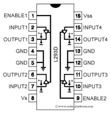
The Future of Industrial Automation

The Future of Industrial Automation

Click for Jim Pinto Biography Since the turn of the century, the global recession has affected most businesses, including industrial automation. After four years of the new millennium, here are my views on the directions in which the automation industry is moving.
The rear-view mirror
Because of the relatively small production volumes and huge varieties of applications, industrial automation typically utilizes new technologies developed in other markets. Automation companies tend to customize products for specific applications and requirements. So the innovation comes from targeted applications, rather than any hot, new technology.
Over the past few decades, some innovations have indeed given industrial automation new surges of growth: The programmable logic controller (PLC) – developed by Dick Morley and others – was designed to replace relay-logic; it generated growth in applications where custom logic was difficult to implement and change. The PLC was a lot more reliable than relay-contacts, and much easier to program and reprogram. Growth was rapid in automobile test-installations, which had to be re-programmed often for new car models. The PLC has had a long and productive life – some three decades – and (understandably) has now become a commodity.
At about the same time that the PLC was developed, another surge of innovation came through the use of computers for control systems. Mini-computers replaced large central mainframes in central control rooms, and gave rise to "distributed" control systems (DCS), pioneered by Honeywell with its TDC 2000. But, these were not really "distributed" because they were still relatively large clumps of computer hardware and cabinets filled with I/O connections.
The arrival of the PC brought low-cost PC-based hardware and software, which provided DCS functionality with significantly reduced cost and complexity. There was no fundamental technology innovation here—rather, these were innovative extensions of technology developed for other mass markets, modified and adapted for industrial automation requirements.
On the sensor side were indeed some significant innovations and developments which generated good growth for specific companies. With better specifications and good marketing, Rosemount's differential pressure flow-sensor quickly displaced lesser products. And there were a host of other smaller technology developments that caused pockets of growth for some companies. But few grew beyond a few hundred million dollars in annual revenue.
Automation software has had its day, and can't go much further. No "inflection point" here. In the future, software will embed within products and systems, with no major independent innovation on the horizon. The plethora of manufacturing software solutions and services will yield significant results, but all as part of other systems.
So, in general, innovation and technology can and will reestablish growth in industrial automation. But, there won't be any technology innovations that will generate the next Cisco or Apple or Microsoft.
We cannot figure out future trends merely by extending past trends; it’s like trying to drive by looking only at a rear-view mirror. The automation industry does NOT extrapolate to smaller and cheaper PLCs, DCSs, and supervisory control and data acquisition systems; those functions will simply be embedded in hardware and software. Instead, future growth will come from totally new directions.
New technology directions
Industrial automation can and will generate explosive growth with technology related to new inflection points: nanotechnology and nanoscale assembly systems; MEMS and nanotech sensors (tiny, low-power, low-cost sensors) which can measure everything and anything; and the pervasive Internet, machine to machine (M2M) networking.
Real-time systems will give way to complex adaptive systems and multi-processing. The future belongs to nanotech, wireless everything, and complex adaptive systems.
Major new software applications will be in wireless sensors and distributed peer-to-peer networks – tiny operating systems in wireless sensor nodes, and the software that allows nodes to communicate with each other as a larger complex adaptive system. That is the wave of the future.
The fully-automated factory
Automated factories and processes are too expensive to be rebuilt for every modification and design change – so they have to be highly configurable and flexible. To successfully reconfigure an entire production line or process requires direct access to most of its control elements – switches, valves, motors and drives – down to a fine level of detail.
The vision of fully automated factories has already existed for some time now: customers order online, with electronic transactions that negotiate batch size (in some cases as low as one), price, size and color; intelligent robots and sophisticated machines smoothly and rapidly fabricate a variety of customized products on demand.
The promise of remote-controlled automation is finally making headway in manufacturing settings and maintenance applications. The decades-old machine-based vision of automation – powerful super-robots without people to tend them – underestimated the importance of communications. But today, this is purely a matter of networked intelligence which is now well developed and widely available.
Communications support of a very high order is now available for automated processes: lots of sensors, very fast networks, quality diagnostic software and flexible interfaces – all with high levels of reliability and pervasive access to hierarchical diagnosis and error-correction advisories through centralized operations.
The large, centralized production plant is a thing of the past. The factory of the future will be small, movable (to where the resources are, and where the customers are). For example, there is really no need to transport raw materials long distances to a plant, for processing, and then transport the resulting product long distances to the consumer. In the old days, this was done because of the localized know-how and investments in equipment, technology and personnel. Today, those things are available globally.
Hard truths about globalization
The assumption has always been that the US and other industrialized nations will keep leading in knowledge-intensive industries while developing nations focus on lower skills and lower labor costs. That's now changed. The impact of the wholesale entry of 2.5 billion people (China and India) into the global economy will bring big new challenges and amazing opportunities.
Beyond just labor, many businesses (including major automation companies) are also outsourcing knowledge work such as design and engineering services. This trend has already become significant, causing joblessness not only for manufacturing labor, but also for traditionally high-paying engineering positions.
Innovation is the true source of value, and that is in danger of being dissipated – sacrificed to a short-term search for profit, the capitalistic quarterly profits syndrome. Countries like Japan and Germany will tend to benefit from their longer-term business perspectives. But, significant competition is coming from many rapidly developing countries with expanding technology prowess. So, marketing speed and business agility will be offsetting advantages.
The winning differences
In a global market, there are three keys that constitute the winning edge:
  • Proprietary products: developed quickly and inexpensively (and perhaps globally), with a continuous stream of upgrade and adaptation to maintain leadership.
  • High-value-added products: proprietary products and knowledge offered through effective global service providers, tailored to specific customer needs.
  • Global yet local services: the special needs and custom requirements of remote customers must be handled locally, giving them the feeling of partnership and proximity.
To implementing these directions demands management and leadership abilities that are different from old, financially-driven models. In the global economy, automation companies have little choice – they must find more ways and means to expand globally. To do this they need to minimize domination of central corporate cultures, and maximize responsiveness to local customer needs. Multi-cultural countries, like the U.S., will have significant advantages in these important business aspects.
In the new and different business environment of the 21st century, the companies that can adapt, innovate and utilize global resources will generate significant growth and success.
Related links:
Credits to: www.automation.com

ACTUATORS - DC MOTORS TUTORIAL

ACTUATORS - DC MOTORS TUTORIAL
DC Motor
From the start, DC motors seem quite simple. Apply a voltage to both terminals, and weeeeeeee it spins. But what if you want to control which direction the motor spins? Correct, you reverse the wires. Now what if you want the motor to spin at half that speed? You would use less voltage. But how would you get a robot to do those things autonomously? How would you know what voltage a motor should get? Why not 50V instead of 12V? What about motor overheating? Operating motors can be much more complicated than you think.
Voltage
You probably know that DC motors are non-polarized - meaning that you can reverse voltage without any bad things happening. Typical DC motors are rated from about 6V-12V. The larger ones are often 24V or more. But for the purposes of a robot, you probably will stay in the 6V-12V range. So why do motors operate at different voltages? As we all know (or should), voltage is directly related to motor torque. More voltage, higher the torque. But don't go running your motor at 100V cause thats just not nice. A DC motor is rated at the voltage it is most efficient at running. If you apply too few volts, it just wont work. If you apply too much, it will overheat and the coils will melt. So the general rule is, try to apply as close to the rated voltage of the motor as you can. Also, although a 24V motor might be stronger, do you really want your robot to carry a 24V battery (which is heavier and bigger) around? My recommendation is do not surpass 12V motors unless you really really need the torque.
El-Cheapo DC Motor
Current
As with all circuitry, you must pay attention to current. Too little, and it just won't work. Too much, and you have meltdown. When buying a motor, there are two current ratings you should pay attention to. The first is operating current. This is the average amount of current the motor is expected to draw under a typical torque. Multiply this number by the rated voltage and you will get the average power draw required to run the motor. The other current rating which you need to pay attention to is the stall current. This is when you power up the motor, but you put enough torque on it to force it to stop rotating. This is the maximum amount of current the motor will ever draw, and hence the maximum amount of power too. So you must design all control circuitry capable of handling this stall current. Also, if you plan to constantly run your motor, or run it higher than the rated voltage, it is wise to heat sink your motor to keep the coils from melting.
Power Rating
How high of a voltage can you over apply to a motor? Well, all motors are (or at least should be) rated at a certain wattage. Wattage is energy. Innefficieny of energy conversion directly relates to heat output. Too much heat, the motor coils melt. So the manufacturers of [higher quality] motors know how much wattage will cause motor failure, and post this on the motor spec sheets. Do experimental tests to see how much current your motor will draw at a desired voltage.
The equation is:
    Power (watts) = Voltage * Current
Power Spikes
There is a special case for DC motors that change directions. To reverse the direction of the motor, you must also reverse the voltage. However the motor has a built up inductance and momentum which resists this voltage change. So for the short period of time it takes for the motor to reverse direction, there is a large power spike. The voltage will spike double the operating voltage. The current will go to around stall current. The moral of this is design your robot power regulation circuitry properly to handle any voltage spikes.
Geared DC Motor
Torque
When buying a DC motor, there are two torque value ratings which you must pay attention to. The first is operating torque. This is the torque the motor was designed to give. Usually it is the listed torque value. The other rated value is stall torque. This is the torque required to stop the motor from rotating. You normally would want to design using only the operating torque value, but there are occasions when you want to know how far you can push your motor. If you are designing a wheeled robot, good torque means good acceleration. My personal rule is if you have 2 motors on your robot, make sure the stall torque on each is enough to lift the weight of your entire robot times your wheel radius. Always favor torque over velocity. Remember, as stated above, your torque ratings can change depending on the voltage applied. So if you need a little more torque to crush that cute kitten, going 20% above the rated motor voltage value is fairly safe (for you, not the kitten). Just remember that this is less efficient, and that you should heat sink your motor.
Velocity
Velocity is very complex when it comes to DC motors. The general rule is, motors run the most efficient when run at the highest possible speeds. Obviously however this is not possible. There are times we want our robot to run slowly. So first you want gearing - this way the motor can run fast, yet you can still get good torque out of it. Unfortunately gearing automatically reduces efficiency no higher than about 90%. So include a 90% speed and torque reduction for every gear meshing when you calculate gearing. For example, if you have 3 spur gears, therefore meshing together twice, you will get a 90% x 90% = 81% efficiency. The voltage and applied torque resistance obviously also affects speed.
Right Angle DC Motor
Control Methods
The most important of DC motor control techniques is the H-Bridge.Refer previous post for making a motor driver circuit. After you have your H-Bridge hooked up to your motor, to determine your wheel velocity/position you must use an encoder. And lastly, you should read up on good DC Motor Braking methods.
Other Information
Place small microfarad capacitors across motor leads to extend motor life. This works really well with noisy and other el-cheapo motors, almost doubling motor life. However there is much less improvement using this technique with the more expensive higher end motors.

Monday, 29 July 2013

Step by step instructions for building Motor Driver circuit...................

Dual H-bridge Motor Driver - L293D IC


Motor Driver and H-bridge basics

Generally, even the simplest robot requires a motor to rotate a wheel or performs particular action. Motor Control using NPN TransistorSince motors require more current then the microcontroller pin can typically generate, you need some type of a switch (Transistors, MOSFET, Relay etc.,) which can accept a small current, amplify it and generate a larger current, which further drives a motor. This entire process is done by what is known as a motor driver.
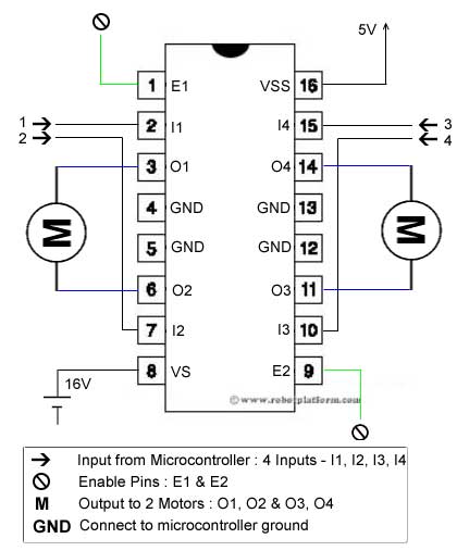
Motor driver is basically a current amplifier which takes a low-current signal from the microcontroller and gives out a proportionally higher current signal which can control and drive a motor. In most cases, a transistor can act as a switch and perform this task which drives the motor in a single direction.
Turning a motor ON and OFF requires only one switch to control a single motor in a single direction. What if you want your motor to reverse its direction? The simple answer is to reverse its polarity. This can be achieved by using four switches that are arranged in an intelligent manner such that the circuit not only drives the motor, but also controls its direction. Out of many, one of the most common and clever design is a H-bridge circuit where transistors are arranged in a shape that resembles the English alphabet "H".H-bridge
As you can see in the image, the circuit has four switches A, B, C and D. Turning these switches ON and OFF can drive a motor in different ways.
  1. Turning on Switches A and D makes the motor rotate clockwise
  2. Turning on Switches B and C makes the motor rotate anti-clockwise
  3. Turning on Switches A and B will stop the motor (Brakes)
  4. Turning off all the switches gives the motor a free wheel drive
  5. Lastly turning on A & C at the same time or B & D at the same time shorts your entire circuit. So, do not attempt this.
H-bridges can be built from scratch using relays, mosfets, field effect transistors (FET), bi-polar junction transistors (BJT), etc. But if your current requirement is not too high and all you need is a single package which does the job of driving a small DC motor in two directions, then all you need is a L293D IC. This single inexpensive package can interface not one, but two DC motors. L293, L293B and few other versions also does the same job, but pick the L293D version as this one has an inbuilt flyback diode which protects the driving transistors from voltage spikes that occur when the motor coil is turned off.
Introduction to L293D ICL293D Skeleton
L293D IC generally comes as a standard 16-pin DIP (dual-in line package). This motor driver IC can simultaneously control two small motors in either direction; forward and reverse with just 4 microcontroller pins (if you do not use enable pins). Some of the features (and drawbacks) of this IC are:
  1. Output current capability is limited to 600mA per channel with peak output current limited to 1.2A (non-repetitive). This means you cannot drive bigger motors with this IC. However, most small motors used in hobby robotics should work. If you are unsure whether the IC can handle a particular motor, connect the IC to its circuit and run the motor with your finger on the IC. If it gets really hot, then beware... Also note the words "non-repetitive"; if the current output repeatedly reaches 1.2A, it might destroy the drive transistors.
  2. Supply voltage can be as large as 36 Volts. This means you do not have to worry much about voltage regulation.
  3. L293D has an enable facility which helps you enable the IC output pins. If an enable pin is set to logic high, then state of the inputs match the state of the outputs. If you pull this low, then the outputs will be turned off regardless of the input states
  4. The datasheet also mentions an "over temperature protection" built into the IC. This means an internal sensor senses its internal temperature and stops driving the motors if the temperature crosses a set point
  5. Another major feature of L293D is its internal clamp diodes. This flyback diode helps protect the driver IC from voltage spikes that occur when the motor coil is turned on and off (mostly when turned off)
  6. The logical low in the IC is set to 1.5V. This means the pin is set high only if the voltage across the pin crosses 1.5V which makes it suitable for use in high frequency applications like switching applications (upto 5KHz)
  7. Lastly, this integrated circuit not only drives DC motors, but can also be used to drive relay solenoids, stepper motors etc.
L293D Connections
The circuit shown to the right is the most basic implementation of L293D IC. There are 16 pins sticking out of this IC and we have to understand the functionality of each pin before implementing this in a circuit
  1. Pin1 and Pin9 are "Enable" pins. They should be connected to +5V for the drivers to function. If they pulled low (GND), then the outputs will be turned off regardless of the input states, stopping the motors. If you have two spare pins in your microcontroller, connect these pins to the microcontroller, or just connect them to regulated positive 5 Volts.
  2. Pin4, Pin5, Pin12 and Pin13 are ground pins which should ideally be connected to microcontroller's ground.
  3. Pin2, Pin7, Pin10 and Pin15 are logic input pins. These are control pins which should be connected to microcontroller pins. Pin2 and Pin7 control the first motor (left); Pin10 and Pin15 control the second motor(right).
  4. Pin3, Pin6, Pin11, and Pin14 are output pins. Tie Pin3 and Pin6 to the first motor, Pin11 and Pin14 to second motor
  5. Pin16 powers the IC and it should be connected to regulated +5Volts
  6. L293D ConnectionsPin8 powers the two motors and should be connected to positive lead of a secondary battery. As per the datasheet, supply voltage can be as high as 36 Volts.
Truth table
I have shown you where to connect the motors, battery and the microcontroller. But how do we control the direction of these motors? Let us take an example:
Suppose you need to control the left motor which is connected to Pin3 (O1) and Pin6 (O2). As mentioned above, we require three pins to control this motor - Pin1 (E1), Pin2 (I1) and Pin7 (I2). Here is the truth table representing the functionality of this motor driver.
Pin 1 Pin 2 Pin 7 Function
High High Low Turn Anti-clockwise (Reverse)
High Low High Turn clockwise (Forward)
High High High Stop
High Low Low Stop
Low X X Stop

  • High ~+5V, Low ~0V, 
  • X=Either high or low (don't care)
In the above truth table you can observe that if Pin1 (E1) is low then the motor stops, irrespective of the states on Pin2 and Pin7. Hence it is essential to hold E1 high for the driver to function, or simply connect enable pins to positive 5 volts.
With Pin1 high, if Pin2 is set high and Pin7 is pulled low, then current flows from Pin2 to Pin7 driving the motor in anti-clockwise direction. If the states of Pin2 and Pin7 are flipped, then current flows from Pin7 to Pin2 driving the motor in clockwise direction.
The above concept holds true for other side of the IC too. Connect your motor to Pin11 and Pin14; Pin10 and Pin15 are input pins, and Pin9 (E2) enables the driver.


Parts required


Parts Details Quantity
L293D IC Motor Driver IC 1
16 Pin Socket 8x2 DIP Socket 1
Perforated board With 20x12 or more holes 1
Connecting wires Any color of your choice 10-12 small pieces
7805 Linear Voltage Regulator 1
Male breakaway headers 40 pin single row headers 1
Solder Lead / Lead free 50-100 gms
Solder Iron Preferably temperature controlled 1
Building the circuit - Part I

L293D Schematic
Let's begin building the circuit. First, add 16 pin socket to the board as shown in the image. As usual, click on any image for an enlarged view with higher resolution. If the step requires soldering, then the soldered part is highlighted to help you with soldering.
Add socket into PCB
Solder first and 16th pin of the socket to copper side of the board.
Solder socket
Add two 2-pin headers (two 2 pin headers) to the left of socket. Make sure there is at least a gap of two holes between socket and header.
Add 4 headers to left

Solder horizontal pins together.
The vertical two pins will be later used to connect the first motor. The other two pins are there in case we need to use this output for some other reason. If you do not need this, you can use a single 2-pin header and plug it vertically and individually solder the two pins to the board.
Solder left headers
Add two more 2-pin headers to the right side of the socket with a minimum gap of two holes between socket and header. The gap makes it easier to plug other female headers once the board is completed.
Add 4 more headers to right
Solder these two headers similar to the left headers
Solder right headers
Now solder the bottom pins of two headers on either side to Pin6 and Pin11 of the IC, as shown in the image.
Connect to pins
Add two more 2-pin headers to either side of the board. These two headers are input pins which are later connected to microcontroller.
Add headers above existing headers
Solder each pin of the header to the board, but take care not to solder them together. As shown in the image, solder the top two header pins on either side to Pin2 and Pin15 respectively.
Solde two four headers
We need two more 2-pin headers, one header for enable pins and other for +5V. Push the two 2-pin headers as pictured below. Let the first two vertical pins be in the same line as the socket pins.

Observe carefully how the soldering happens from here on if you are not sure what is happening. I can assure that you would have a complete working circuit if you follow the tutorial exactly.
The top two header pins are soldered together. One of the pin in bottom header is soldered to Pin1 of the socket. Click on the image to understand what I mean.

We will add two more pins for powering the circuit (we will call these two pins as Power pins to make soldering easier).

Solder each pin of the header to the board, but do not short them.

Add a 7805 voltage regulator such that the center pin is in line with power pins. I have bent the regulator to make it look compact (or I just like to keep it like that). If you do not want to bend it, keep it upright.
The top lead of regulator is input (Vin), middle lead is ground (Gnd) and the bottom lead is output (Vout) which gives a regulated +5volts.

Bend the regulator leads as shown. The middle pin almost touches one of the power pins. If the regulator lead (the middle one) is too long such that it touches both the power pins, cut it short. Vin should also be bent in the same fashion. Vout is bent such that it touches the headers above enable pins.


Add a red wire (or any color) to connect Pin9 to enable pin. Push one side of the wire next to Pin9 and the other side to a hole above the socket (as shown below). I have used a marker to mark the pins to avoid confusion.

Solder the pins and wires carefully as mentioned below:
  1. Solder one side of the wire to Pin9 (Click to enlarge the image. The bottom highlighted part)
  2. The other side of the wire will be soldered to second pin of enable header
  3. Vout from regulator (bottom lead) is soldered to header above enable pins
  4. Gnd from regulator (middle lead) is connected to left power pin (left pin if the copper side of board is on top)
  5. Vin from regulator (top lead) is connected to right power pin
I have highlighted Vin in RED just to make sure you do not solder ground and power pins together. If you do connect, you will end up shorting the circuit and frying it.

Add a red wire running from positive of power pin to Pin8 of the socket.

Solder one end of red wire to positive of power pin and the other end to Pin8

Add another black wire to connect ground. Push one end below the ground of power pins and the other end next to Pin4 of the socket

Solder the black wire as shown here. One side connects ground of power pins and other side connects Pin4.

Cut and trim a small wire and place it in two holes next to Pin3 and Pin5 of the socket.

This wire connects output1 of L293D IC to header pin. Solder top side of the wire to Pin3 and bottom side of the wire to first output header pin on the left. (marked O1)

Add a slightly larger black wire next to previously added black wire such that the top end of the wire is in the same row of the black small wire, but the bottom end is two holes next to Pin7 of the socket.


Solder the top side of this wire to second pin of input header (marked I2) and solder the bottom end to Pin7 of the socket.

Add a similar wire to right side of the board as shown in the image. The top end of the wire should be pushed next to Pin14 and bottom end next to Pin10 of the socket. This connects input pin of IC to right input pin (marked I3)

Solder top end of the wire to header pin (marked I3) and bottom end to Pin10.

You are almost done!! Push the top end of a wire into a hole next to Pin14 and the bottom end next to Pin12 of the socket.

Solder the top end to Pin14 of the socket and bottom end to right output header pin (marked O4)

Since we need to power the components inside the IC, add a red wire which connects +5V to Pin16 of the socket. The two pins above enable pins are already connected to +5V and we can push one end of the wire to a hole next to that and other end next to Pin16.

Solder Pin16 to bottom end of the wire while top end of the wire is soldered to header pins above enable pins, which is further connected to Vout of regulator.

Lastly, solder all four ground pins together. Pin4, Pin5, Pin12 and Pin13 are all ground pins; solder them together.

DONE!! You have a completed (and hopefully working) L293D motor driver board which can control two motors.
As you can see in the image, I have drilled four holes (actually five including one below the regulator) and pushed four screws into it.

Whenever you implement it, always remember that enable pins are not connected. Either connect enable pins to your microcontroller pins and programmatically set it high, or use a jumper and connect each enable pin to the header just above it (which is connected to +5V)
Here is the implementation on one of my robots. You can also see that there is another small board which is also a motor driver, but the board is built using PCB etching method.

Here is the schematic I had developed. If anybody is interested in building a board using PCB Etching method, or any other method, please request in the forum and I will share the complete board designs.