Dual H-bridge Motor Driver - L293D IC
Motor Driver and H-bridge basics
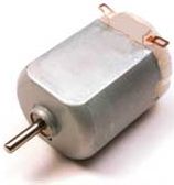
Generally, even the simplest robot requires a motor to rotate a wheel or performs particular action.
Since
motors require more current then the microcontroller pin can typically
generate, you need some type of a switch (Transistors, MOSFET, Relay
etc.,) which can accept a small current, amplify it and generate a
larger current, which further drives a motor. This entire process is
done by what is known as a
motor driver.
Motor driver is basically a current amplifier which takes a
low-current signal from the microcontroller and gives out a
proportionally higher current signal which can control and drive a
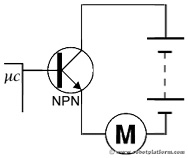
motor. In most cases, a transistor can act as a switch and perform this
task which drives the motor in a single direction.
Turning a motor ON and OFF requires only one switch to control a
single motor in a single direction. What if you want your motor to
reverse its direction? The simple answer is to reverse its polarity.
This can be achieved by using four switches that are arranged in an
intelligent manner such that the circuit not only drives the motor, but
also controls its direction. Out of many, one of the most common and
clever design is a H-bridge circuit where transistors are arranged in a
shape that resembles the English alphabet "H".
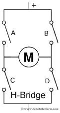
As you can see in the image, the circuit has four switches A, B, C
and D. Turning these switches ON and OFF can drive a motor in different
ways.
- Turning on Switches A and D makes the motor rotate clockwise
- Turning on Switches B and C makes the motor rotate anti-clockwise
- Turning on Switches A and B will stop the motor (Brakes)
- Turning off all the switches gives the motor a free wheel drive
- Lastly turning on A & C at the same time or B & D at the same time shorts your entire circuit. So, do not attempt this.
H-bridges can be built from scratch using relays, mosfets, field
effect transistors (FET), bi-polar junction transistors (BJT), etc. But
if your current requirement is not too high and all you need is a single
package which does the job of driving a small DC motor in two
directions, then all you need is a L293D IC. This single inexpensive
package can interface not one, but two DC motors. L293, L293B and few
other versions also does the same job, but pick the L293D version as
this one has an inbuilt flyback diode which protects the driving
transistors from voltage spikes that occur when the motor coil is turned
off.
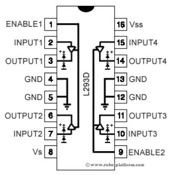
Introduction to L293D IC
L293D IC generally comes as a standard 16-pin DIP (dual-in line
package). This motor driver IC can simultaneously control two small
motors in either direction; forward and reverse with just 4
microcontroller pins (if you do not use enable pins). Some of the
features (and drawbacks) of this IC are:
- Output current capability is limited to 600mA per channel with
peak output current limited to 1.2A (non-repetitive). This means you
cannot drive bigger motors with this IC. However, most small motors used
in hobby robotics should work. If you are unsure whether the IC can
handle a particular motor, connect the IC to its circuit and run the
motor with your finger on the IC. If it gets really hot, then beware...
Also note the words "non-repetitive"; if the current output repeatedly
reaches 1.2A, it might destroy the drive transistors.
- Supply voltage can be as large as 36 Volts. This means you do not have to worry much about voltage regulation.
- L293D has an enable facility which helps you enable the IC output
pins. If an enable pin is set to logic high, then state of the inputs
match the state of the outputs. If you pull this low, then the outputs
will be turned off regardless of the input states
- The datasheet also mentions an "over temperature protection" built
into the IC. This means an internal sensor senses its internal
temperature and stops driving the motors if the temperature crosses a
set point
- Another major feature of L293D is its internal
clamp diodes. This flyback diode helps protect the driver IC from
voltage spikes that occur when the motor coil is turned on and off
(mostly when turned off)
- The logical low in the IC is set to 1.5V. This means the pin is
set high only if the voltage across the pin crosses 1.5V which makes
it suitable for use in high frequency applications like switching
applications (upto 5KHz)
- Lastly, this integrated circuit not only drives DC motors, but can also be used to drive relay solenoids, stepper motors etc.
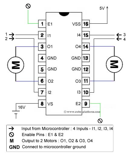
L293D Connections
The circuit shown to the right is the most basic implementation of
L293D IC. There are 16 pins sticking out of this IC and we have to
understand the functionality of each pin before implementing this in a
circuit
- Pin1 and Pin9 are "Enable" pins. They should be connected to +5V
for the drivers to function. If they pulled low (GND), then the outputs
will be turned off regardless of the input states, stopping the motors.
If you have two spare pins in your microcontroller, connect these pins
to the microcontroller, or just connect them to regulated positive 5
Volts.
- Pin4, Pin5, Pin12 and Pin13 are ground pins which should ideally be connected to microcontroller's ground.
- Pin2, Pin7, Pin10 and Pin15 are logic input pins. These are
control pins which should be connected to microcontroller pins. Pin2
and Pin7 control the first motor (left); Pin10 and Pin15 control the
second motor(right).
- Pin3, Pin6, Pin11, and Pin14 are output pins. Tie Pin3 and Pin6 to the first motor, Pin11 and Pin14 to second motor
- Pin16 powers the IC and it should be connected to regulated +5Volts
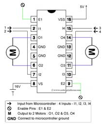 Pin8
powers the two motors and should be connected to positive lead of a
secondary battery. As per the datasheet, supply voltage can be as high
as 36 Volts.
Pin8
powers the two motors and should be connected to positive lead of a
secondary battery. As per the datasheet, supply voltage can be as high
as 36 Volts.
Truth table
I have shown you where to connect the motors, battery and the microcontroller. But how do we control the direction of these motors? Let us take an example:
Suppose you need to control the left motor which is connected to
Pin3 (O1) and Pin6 (O2). As mentioned above, we require three pins to
control this motor - Pin1 (E1), Pin2 (I1) and Pin7 (I2). Here is the
truth table representing the functionality of this motor driver.
- X=Either high or low (don't care)
In the above truth table you can observe that if Pin1 (E1) is low
then the motor stops, irrespective of the states on Pin2 and Pin7. Hence
it is essential to hold E1 high for the driver to function, or simply
connect enable pins to positive 5 volts.
With Pin1 high, if Pin2 is set high and Pin7 is pulled low, then
current flows from Pin2 to Pin7 driving the motor in anti-clockwise
direction. If the states of Pin2 and Pin7 are flipped, then current
flows from Pin7 to Pin2 driving the motor in clockwise direction.
The above concept holds true for other side of the IC too. Connect
your motor to Pin11 and Pin14; Pin10 and Pin15 are input pins, and
Pin9 (E2) enables the driver.
Parts required
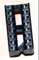
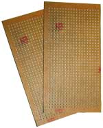
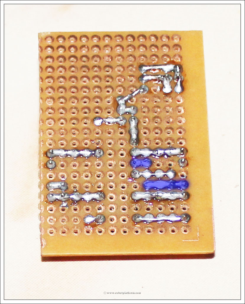
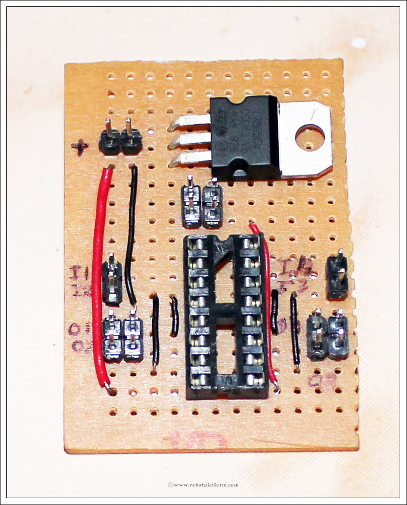
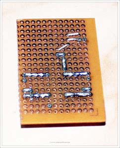
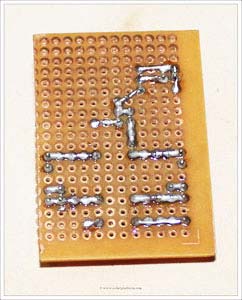
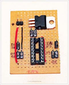
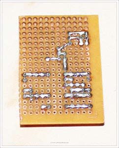
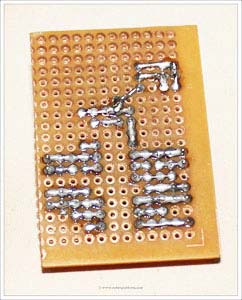
Building the circuit - Part I
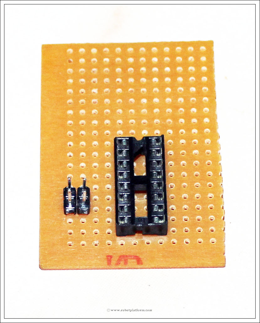
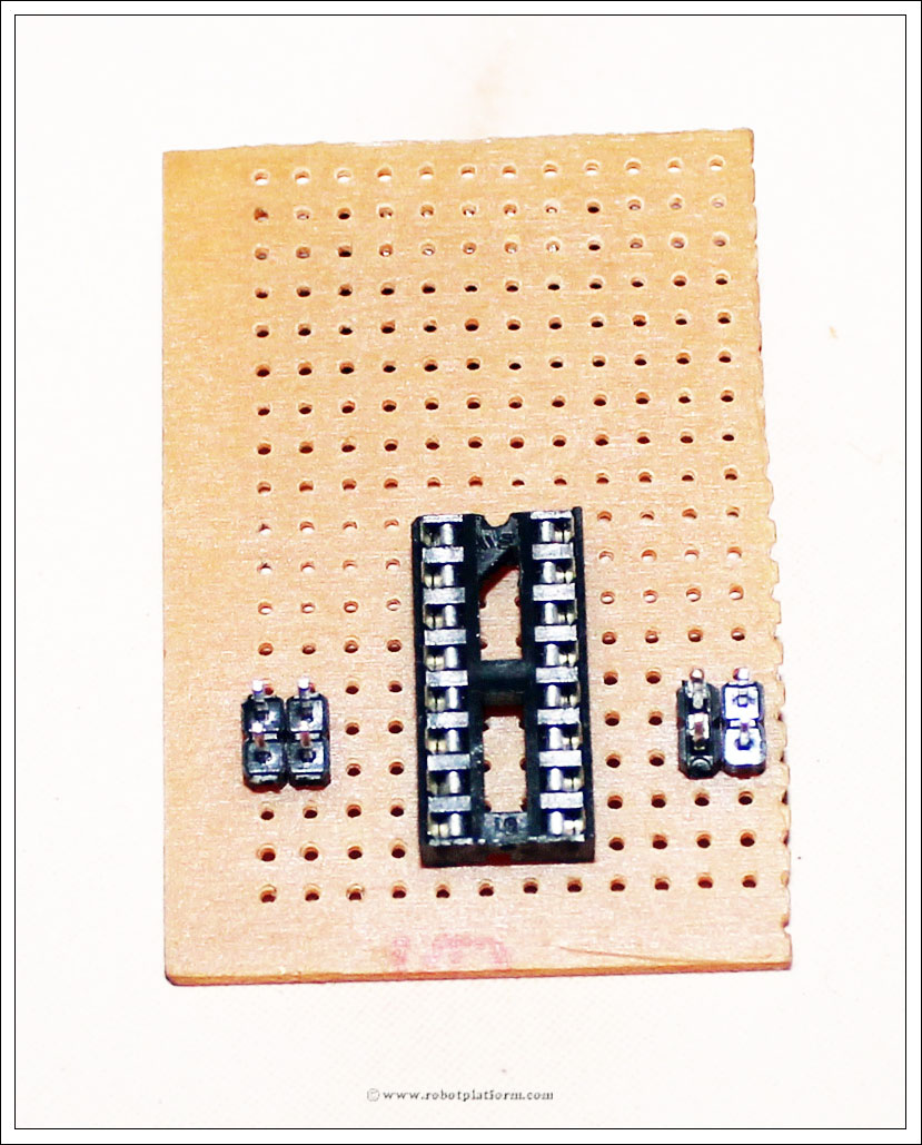
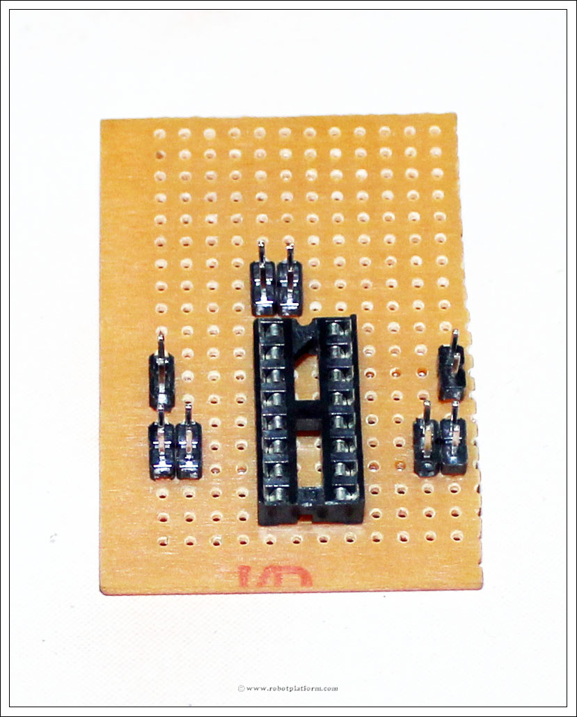
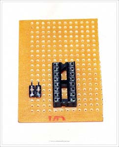
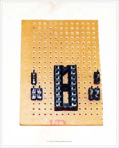
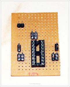
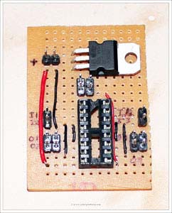
Let's begin building the circuit. First, add 16 pin socket
to the board as shown in the image. As usual, click on any image for an
enlarged view with higher resolution. If the step requires soldering,
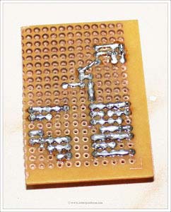
then the soldered part is highlighted to help you with soldering.
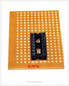
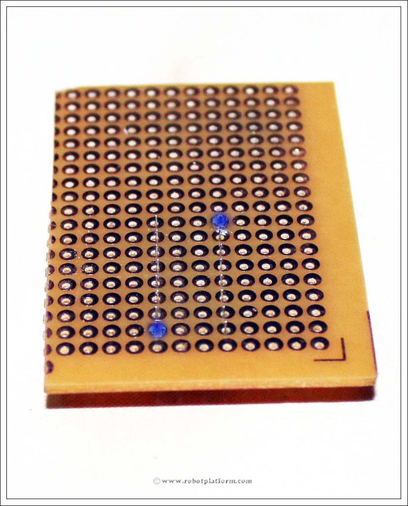
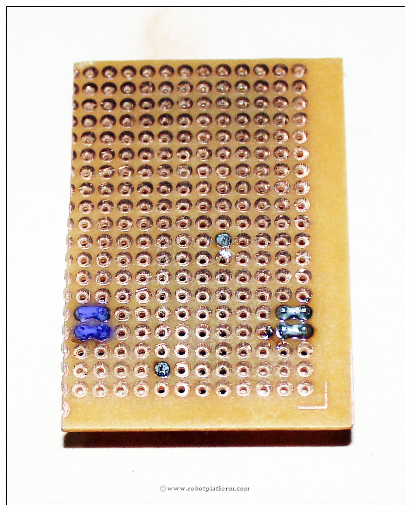
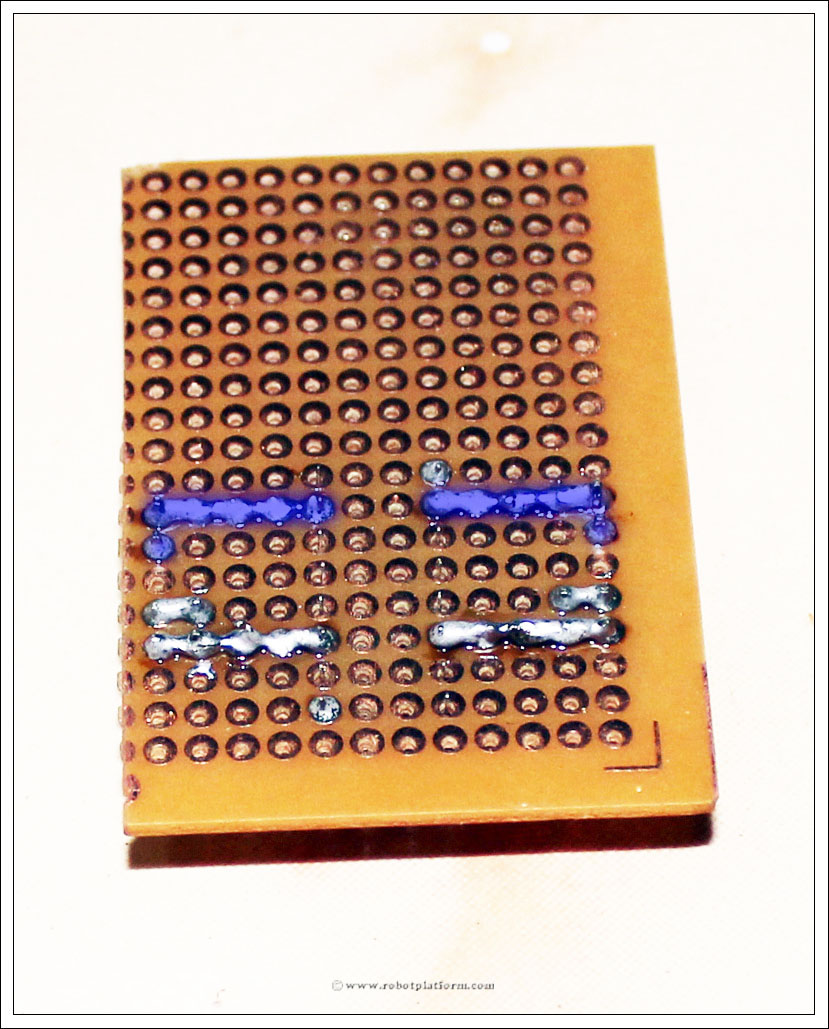
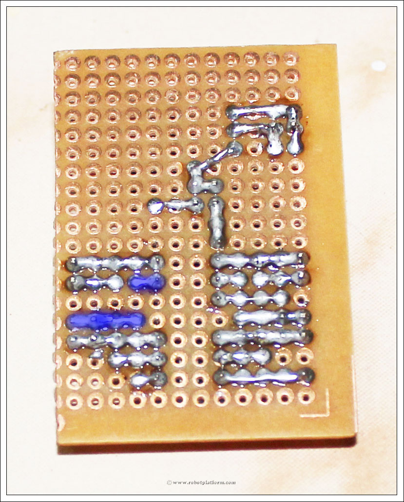
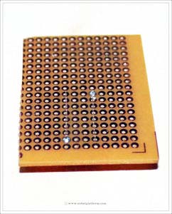
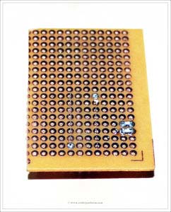
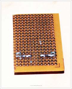
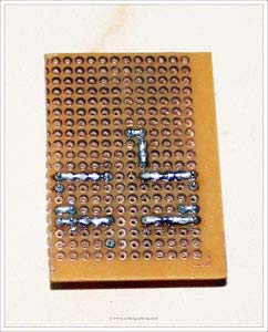
Solder first and 16th pin of the socket to copper side of the board.
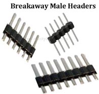
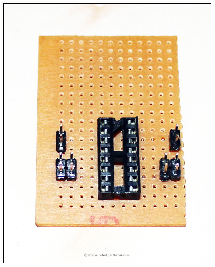
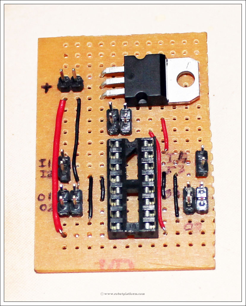
Add two 2-pin headers (two 2 pin headers) to the left of
socket. Make sure there is at least a gap of two holes between socket
and header.
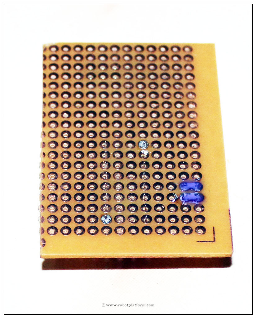
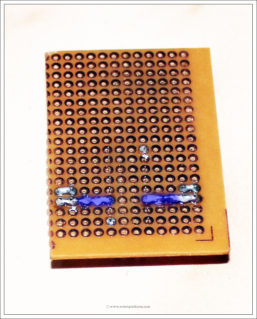
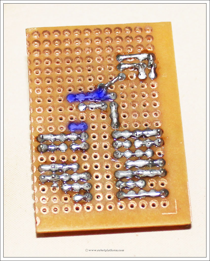
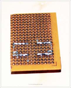
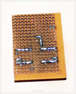
Solder horizontal pins together.
The vertical two pins will be later used to connect the first motor.
The other two pins are there in case we need to use this output for some
other reason. If you do not need this, you can use a single 2-pin
header and plug it vertically and individually solder the two pins to
the board.
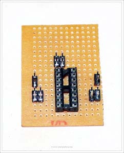
Add two more 2-pin headers to the right side of the socket with a
minimum gap of two holes between socket and header. The gap makes it
easier to plug other female headers once the board is completed.
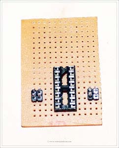
Solder these two headers similar to the left headers
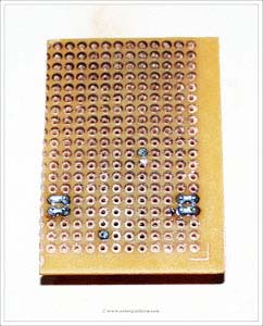
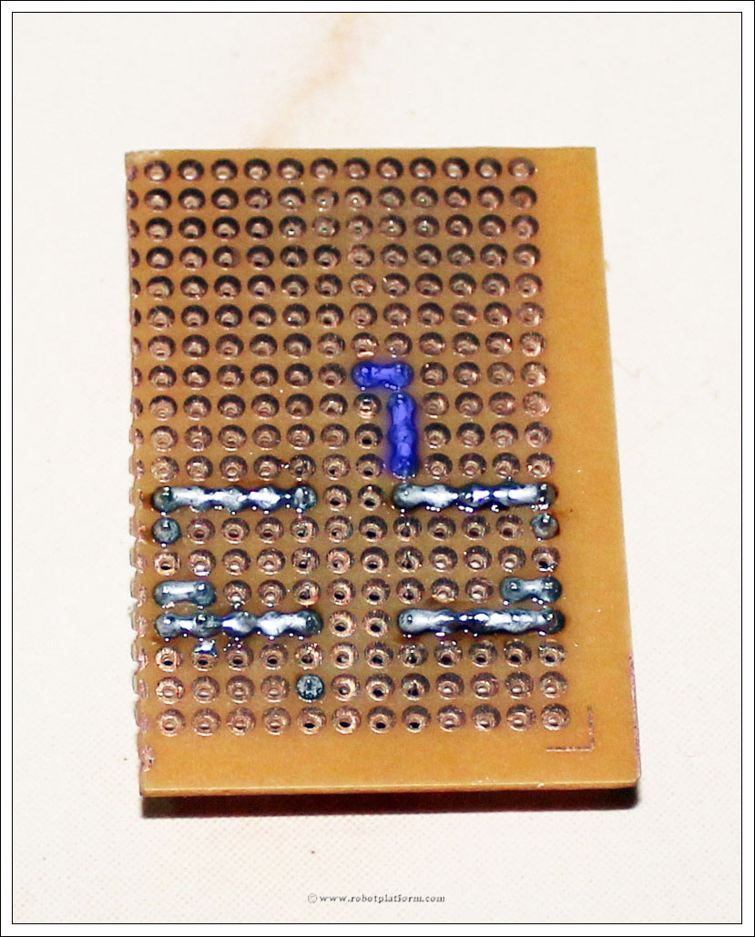
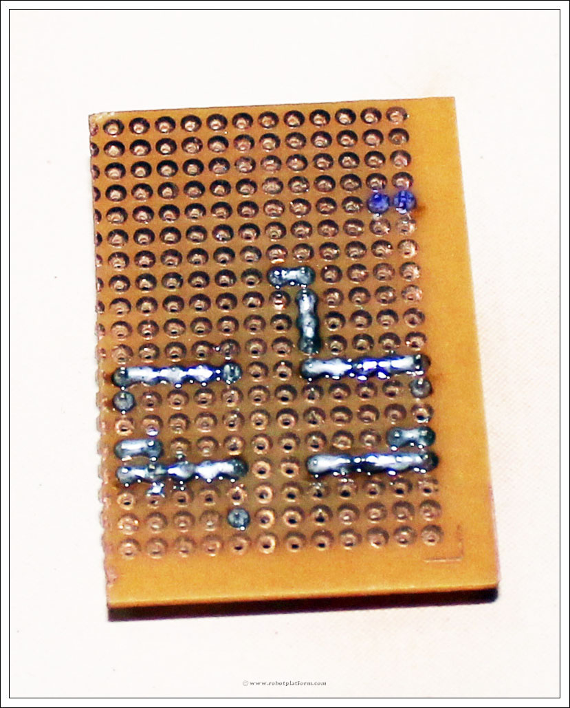
Now solder the bottom pins of two headers on either side to Pin6 and Pin11 of the IC, as shown in the image.
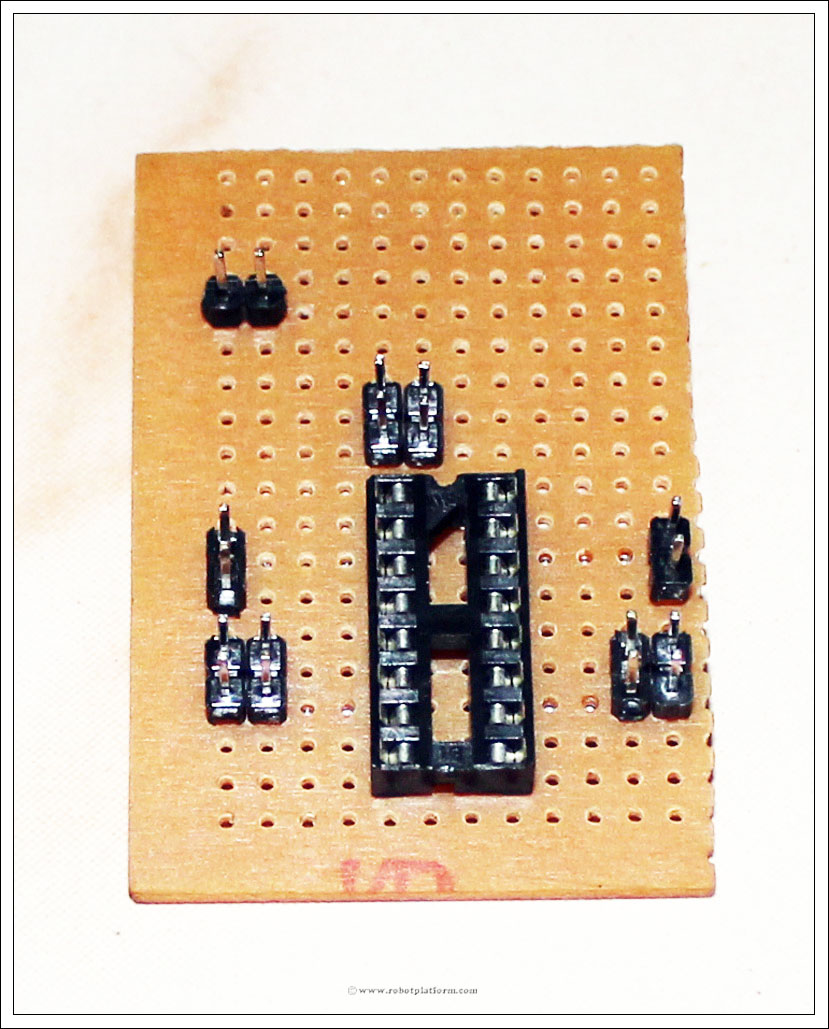
Add two more 2-pin headers to either side of the board. These two
headers are input pins which are later connected to microcontroller.
Solder each pin of the header to the board, but take care not to
solder them together. As shown in the image, solder the top two header
pins on either side to Pin2 and Pin15 respectively.
We need two more 2-pin headers, one header for
enable pins
and other for +5V. Push the two 2-pin headers as pictured below. Let
the first two vertical pins be in the same line as the socket pins.
Observe carefully how the soldering happens from here on if you are
not sure what is happening. I can assure that you would have a complete
working circuit if you follow the tutorial exactly.
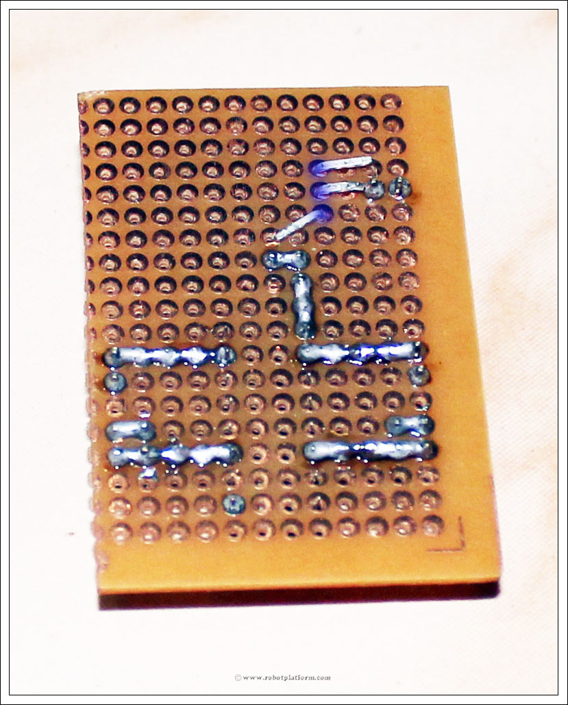
The top two header pins are soldered together. One of the pin in
bottom header is soldered to Pin1 of the socket. Click on the image to
understand what I mean.
We will add two more pins for powering the circuit (we will call these two pins as
Power pins to make soldering easier).
Solder each pin of the header to the board, but do not short them.
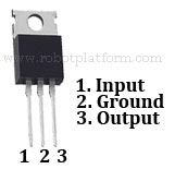
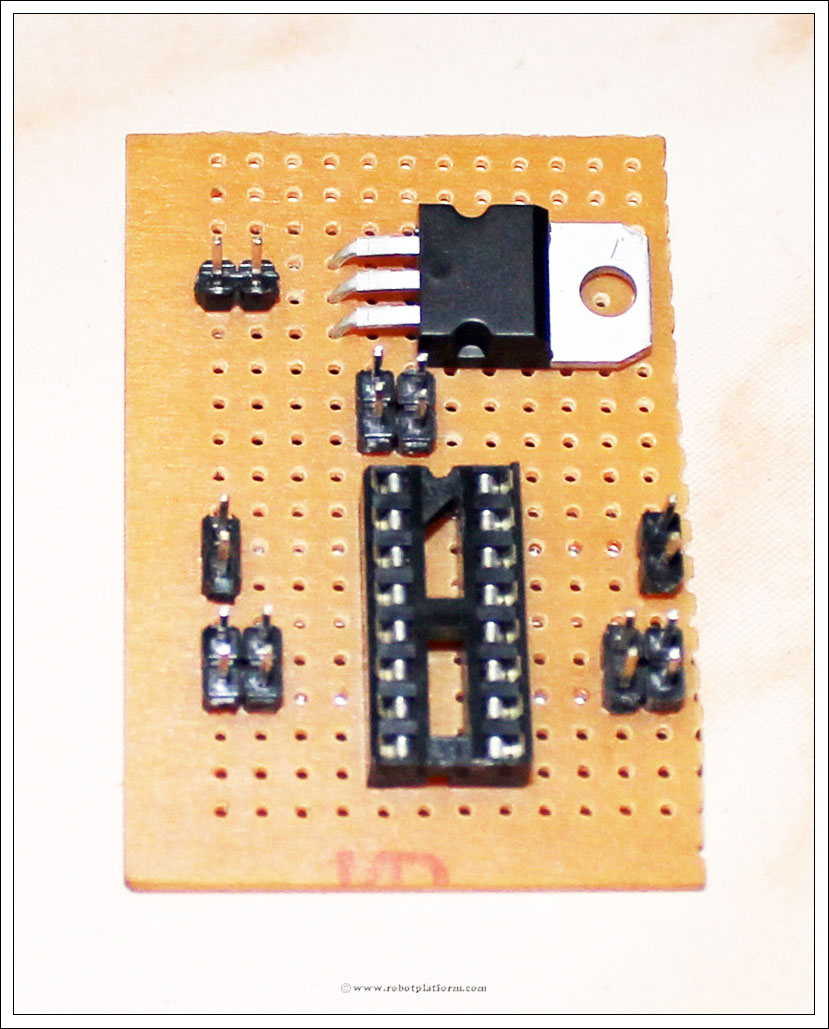
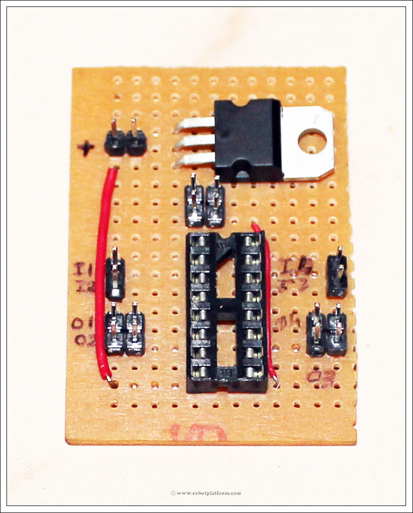
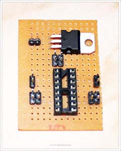
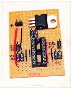
Add a 7805 voltage regulator such that the center pin is in line with
power pins. I have bent the regulator to make it look compact (or I
just like to keep it like that). If you do not want to bend it, keep it
upright.
The top lead of regulator is input (Vin), middle lead is ground
(Gnd) and the bottom lead is output (Vout) which gives a regulated
+5volts.
Bend the regulator leads as shown. The middle pin almost touches one
of the power pins. If the regulator lead (the middle one) is too long
such that it touches both the power pins, cut it short. Vin should also
be bent in the same fashion. Vout is bent such that it touches the
headers above enable pins.
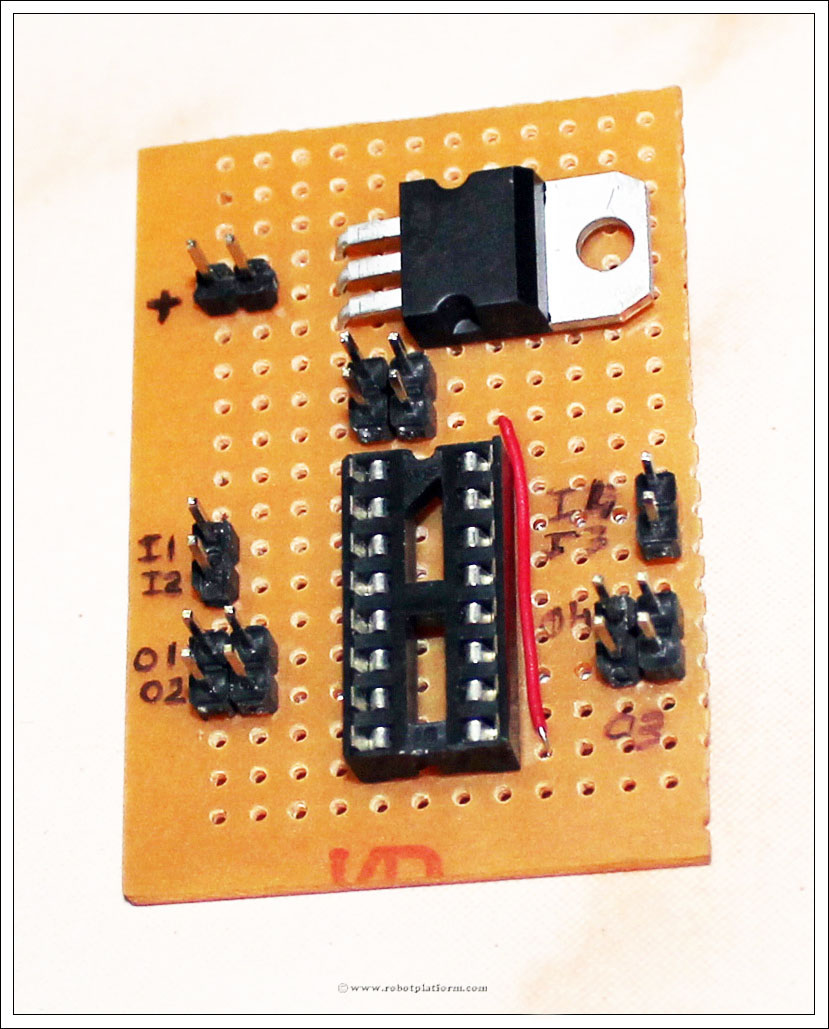
Add a red wire (or any color) to connect
Pin9 to enable pin. Push one side of the wire next to Pin9 and the other
side to a hole above the socket (as shown below). I have used a marker
to mark the pins to avoid confusion.
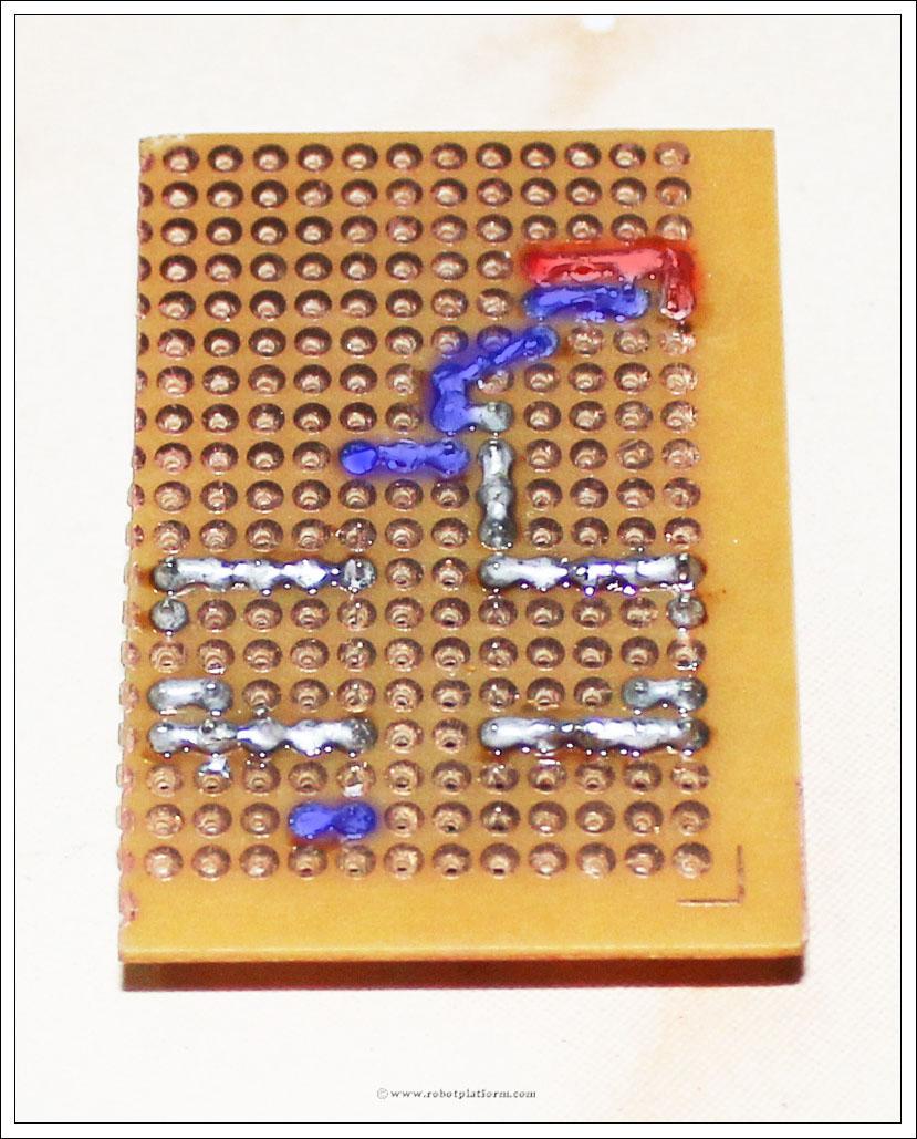
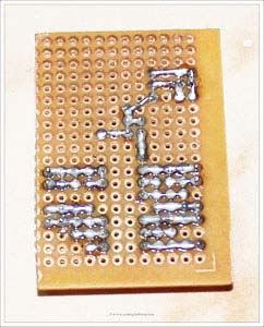
Solder the pins and wires carefully as mentioned below:
- Solder one side of the wire to Pin9 (Click to enlarge the image. The bottom highlighted part)
- The other side of the wire will be soldered to second pin of enable header
- Vout from regulator (bottom lead) is soldered to header above enable pins
- Gnd from regulator (middle lead) is connected to left power pin (left pin if the copper side of board is on top)
- Vin from regulator (top lead) is connected to right power pin
I have highlighted Vin in RED just to make sure you do not
solder ground and power pins together. If you do connect, you will end
up shorting the circuit and frying it.
Add a red wire running from positive of power pin to Pin8 of the socket.
Solder one end of red wire to positive of power pin and the other end to Pin8
Add another black wire to connect ground. Push one end
below the ground of power pins and the other end next to Pin4 of the
socket
Solder the black wire as shown here. One side connects ground of power pins and other side connects Pin4.
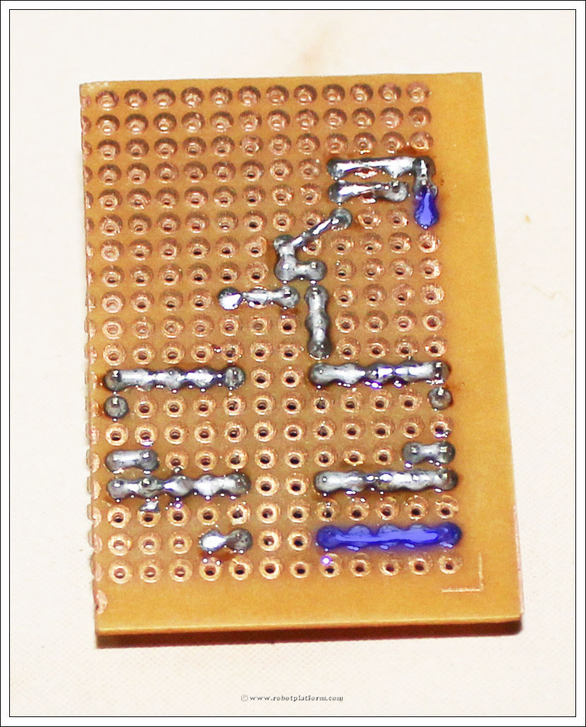
Cut and trim a small wire and place it in two holes next to Pin3 and Pin5 of the socket.
This wire connects output1 of L293D IC to header pin.
Solder top side of the wire to Pin3 and bottom side of the wire to first
output header pin on the left. (marked O1)
Add a slightly larger black wire next to previously added
black wire such that the top end of the wire is in the same row of the
black small wire, but the bottom end is two holes next to Pin7 of the
socket.
Solder the top side of this wire to second pin of input header (marked I2) and solder the bottom end to Pin7 of the socket.
Add a similar wire to right side of the board as shown in the image.
The top end of the wire should be pushed next to Pin14 and bottom end
next to Pin10 of the socket. This connects input pin of IC to right
input pin (marked I3)
Solder top end of the wire to header pin (marked I3) and bottom end to Pin10.
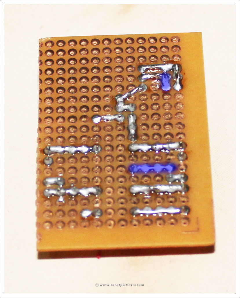
You are almost done!! Push the top end of a wire into a hole next to Pin14 and the bottom end next to Pin12 of the socket.
Solder the top end to Pin14 of the socket and bottom end to right output header pin (marked O4)
Since we need to power the components inside the IC, add a red wire
which connects +5V to Pin16 of the socket. The two pins above enable
pins are already connected to +5V and we can push one end of the wire
to a hole next to that and other end next to Pin16.
Solder Pin16 to bottom end of the wire while top end of the wire is
soldered to header pins above enable pins, which is further connected to
Vout of regulator.
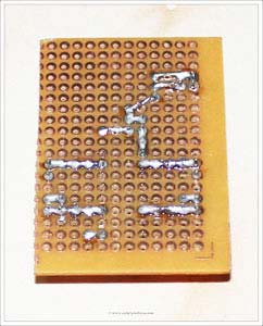
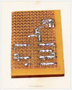
Lastly, solder all four ground pins together. Pin4, Pin5, Pin12 and Pin13 are all ground pins; solder them together.
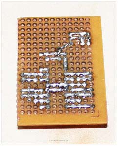
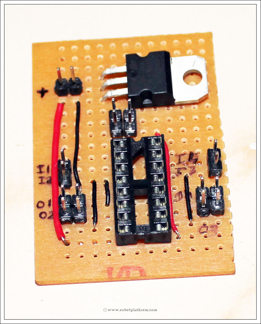
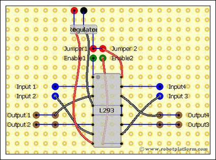
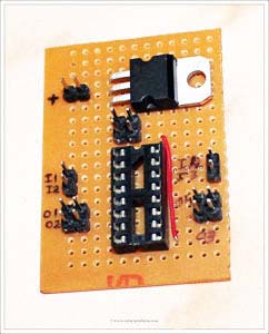
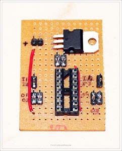
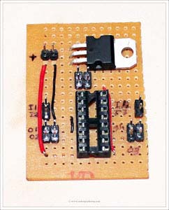
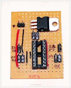
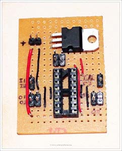
DONE!! You have a completed (and hopefully working) L293D motor driver board which can control two motors.
As you can see in the image, I have drilled four holes (actually five
including one below the regulator) and pushed four screws into it.
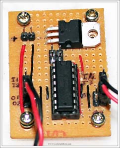
Whenever you implement it, always remember that enable pins are not
connected. Either connect enable pins to your microcontroller pins and
programmatically set it high, or use a jumper and connect each enable
pin to the header just above it (which is connected to +5V)
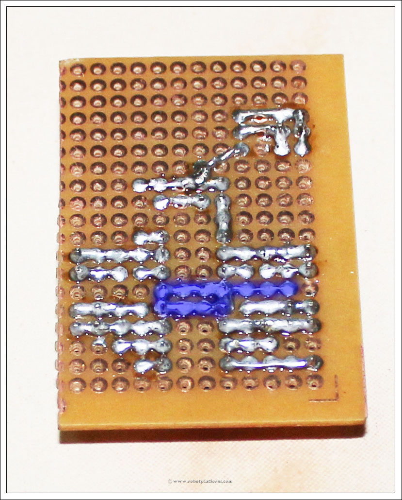
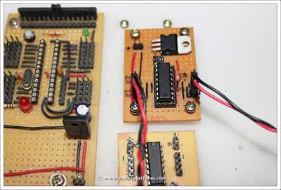
Here is the implementation on one of my robots. You can also see
that there is another small board which is also a motor driver, but the
board is built using PCB etching method.
Here is the schematic I had developed. If anybody is interested in building a board using PCB Etching method, or any other method, please request in the forum and I will share the complete board designs.